Plotting Gain and Phase for a General Voltage Divider


The information presented in this blog post is for educational purposes only. It should not be used for engineering design or relied upon as engineering advice.
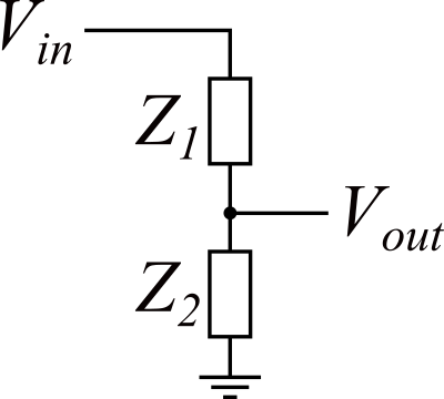
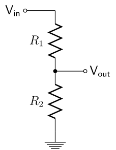
A previous blog post showed how to analyze a resistive voltage divider. This example expands on the previous example to analyze a voltage divider that consists of any combination of resistors, capacitors, and inductors. The main impact of using capacitors and inductors in a voltage divider is that the gain between the output voltage and the input voltage becomes a function of input frequency. Additionally, the impedances for the components become complex numbers and require using the complex number capabilities of EngineeringPaper.xyz.
This general voltage divider example sheet may also be opened in a separate tab.
Plotting Gain and Phase for a General Voltage Divider
by u/mgreminger in EngineeringPaperXYZ
You may also like:
Voltage Divider Calculations with and without Load
The information presented in this blog post is...